Linear valve Recovery and Rebuilding
Repair of Linear Style Selector Valve
| Back |
The Selector Valve (SV) lines up a piston that has a hole in the side (not shown) with the proper stainless tube. The FILL pump them pumps the selected solution into the heating tank. The piston has "o" rings that must be kept lubricated. Most SV problems are caused by a lack of lubrication. When not lubricated, the built up stresses will not allow proper operation and the unit may jam in mid process. The unit will not "initialize".
"Lube"
must be run correctly. After the unit "initializes" push "plus" until "lube" is displayed. Push "start" and wait until the unit displays "please turn off". Turn power switch off, go to the grease fitting on the back of the unit above the line of stainless steel tubes and turn the fitting a half turn. This will push some grease into the piston. Repeat this process 3 or 4 times and then turn unit on and try to process.OPERATION
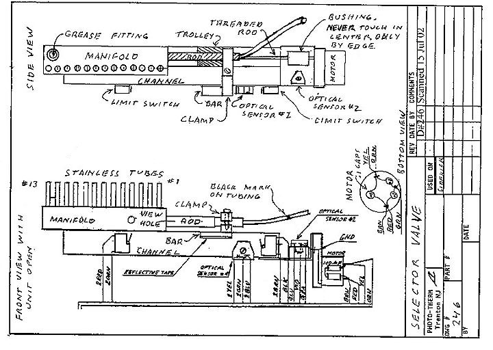
The MOTOR turns the BUSHING and the THREADED ROD, which moves the TROLLEY along a groove in the CHANNEL. The TROLLEY is ATTACHED to the CLAMP which holds the ROD. The ROD is hollow and has a piston, with a hole in its side, mounted on its end (not shown). The turning of the motor positions the piston at the proper stainless tube.
When the unit initializes, OPTICAL SENSOR #1 (OS1) sends out an infra-red light. The motor turns until the BAR with the REFLECTIVE TAPE is sensed by OS1. This is the water position (tube #4).
After that, OPTICAL SENSOR #2 counts MOTOR rotations by sensing a reflective tape on the BUSHING. This positions the piston on any other tube. Never touch the center of the BUSHING. Oils on your hand will give false counts.
RECOVERING A JAMMED SELECTOR VALVE
Save any film in mid process by noting the display to determine where you are in the process. Remove the DRUM. Drain any solution in the DRUM. Put the DRUM in a bucket of water. This puts the film in a safe condition until the unit is fixed.
When the unit is fixed, drain the water out of the DRUM and mount on the unit. Restart the process, move the water bottle tubing to the solution stainless tube that the film has already passed through. Let the process continue automatically.
PHASE ONE
Turn the unit off. Pull off the 1-1/2" black round plug on the right side of the unit. The end of the MANIFOLD is now visible. Use a silicone spray can with an extension tube to spray some silicone inside the MANIFOLD. DO NOT USE WD-40.
Turn the unit on. If it does not initialize, help it start moving by using a pencil to push the piston inside the MANIFOLD. Be careful not to scratch the wall of the manifold. If it initializes, do 3-4 LUBE cycles immediately. Everything is OK.
If it does not initialize, OPEN THE UNIT, unplug from the wall and examine the SV.
VERY VERY IMPORTANT - PROTECT THE PC BOARD BY COVERING WITH PAPER TOWELS AND A SHEET OF PLASTIC WHEN UNIT IS OPEN. A DROP OF SOLUTION ON THE PC BOARD WILL CAUSE SERIOUS PROBLEMS.If the unit still does not initialize, order a rebuilt selector valve linear style, send it in for retrofit of a gat (rotary) selector valve or go to phase 2.
PHASE TWO
Remove the SV (see below). Check the 3 small capacitors on the bottom of the motor. If any one is discolored, remove it. The unit will work without it.
Try to free up the SV by pushing along the EDGE of the BUSHING - is it cracked?
DO NOT TOUCH THE CENTER OF THE BUSHING. Help the motion by pushing on the TROLLEY and CLAMP. Spray silicone lubricant into both ends of the manifold.If you can get the TROLLEY moving, retest. The SV can be tested while the unit is open. All wires going to the SV are low voltage, so you can hold it in your hand. Make sure OPTICAL SENSOR #1 is not facing a bright light in the room. Plug the SV connector into the board, plug in the power to the unit and turn it on. If it initializes, all is OK. Reassemble and run several LUBE cycles.
If it does not initialize, order a rebuilt selector valve linear style, send the unit in for retrofit to a gat (rotary) style selector valve or try phase 3.
PHASE 3
Scratch lines on the ROD on both sides of the CLAMP so you can later accurately reposition (length and rotation) the ROD.
Loosen the screw on the CLAMP and push the ROD and PISTON out of the end of the MANIFOLD. GREASE up the "o" rings with silicone grease (in the syringe provided with the unit) and reassemble the SV. It should now work if the calibration was not lost.
Make sure the unit gets lubed regularly.
PROCEDURES
Opening the unit. Qualified personnel only.
The unit must be opened to reach the internal components. 1. Remove the power cord from the unit and pull at least one battery from the battery holder. Remove all the solution tubing from the stainless tubes on the back of the unit.
SELECTOR VALVE REMOVAL
Open the unit (see OPENING). Cover the PC BOARD with paper towels and a plastic sheet to protect it from getting wet. The SELECTOR VALVE (SV) is now exposed. The tubing from the SV is held against the side of the case by two clamps or wire ties. Cut the nylon wire ties or open the clamps. With a paper towel in hand, remove the SV tubing from the fitting. DO NOT DRIP, especially on the printed circuit board.
Remove the electrical connector of the SV from the PC board. Lift the connector straight up carefully. Do not bend the pins.
The SV is held with 2 screws that are on top of the BODY. Unscrew the 2 screws and carefully remove the SV.
REMOUNTING THE SV
Fasten with the 2 screws. Wire tie (not too tight) or clamp the tubing to the case. The mark on the tubing should line up with the bottom of the lower block. Push the end of the tubing onto the pump.
Replace the electrical connector in the socket marked FLUTE on the PC BOARD. The mark on the connector should be oriented with the lower left corner.
Close up the unit. Do a test processing run.
|
|